
Tagged Under
This Cubase setup template creates:
– a MIDI Track for each of the 16 synth Parts;
– 16 Audio Tracks for the 16 available stereo buses; and,
– it sets up the “MONTAGE Connect” utility to automatically capture (backup/restore) your MONTAGE Performance for the current Project.
Additionally, it sets up a MIDI Track for System Exclusive messages.
In Cubase, go to FILE > NEW PROJECT > RECORDING. Here you can select from the various Project Templates:
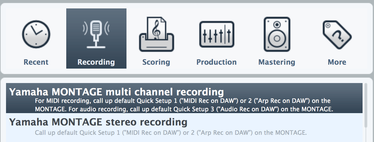
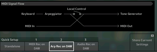
As you can see this TEMPLATE is useful in conjunction with each of the three QUICK SETUPs in the MONTAGE: MIDI REC on DAW, ARP REC on DAW and AUDIO REC on DAW. We will take a close look at how it can serve you as a starting point for different recording Projects. 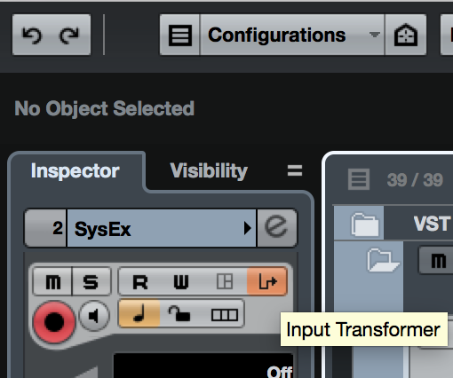
This TEMPLATE makes use of the Cubase Pro’s INPUT TRANSFORMER – a device through which your MIDI data will be sorted and filtered.
In Cubase Pro, the INPUT TRANSFORMER is used to create a situation where each MIDI Track can only record the data as specified: the “Sysex Track”, for example, has the Input Transformer that Filters all but System Exclusive messages. Each of the numbered MIDI Tracks, 01-16, is set to reject all but a single MIDI channel and to reject Sysex:

Normally, a Cubase MIDI Track will record any and all incoming MIDI data, but this template sets up a situation where each MIDI Track can only record data from a specific MIDI Channel, and only the SYSEX Track can document System Exclusive mesages.
The Audio Tracks will only record what you bus to them by making the PART OUTPUT parameter settings in the MONTAGE and routing it via the Track Inspector selection in Cubase. We’ll learn how to do this, as well.
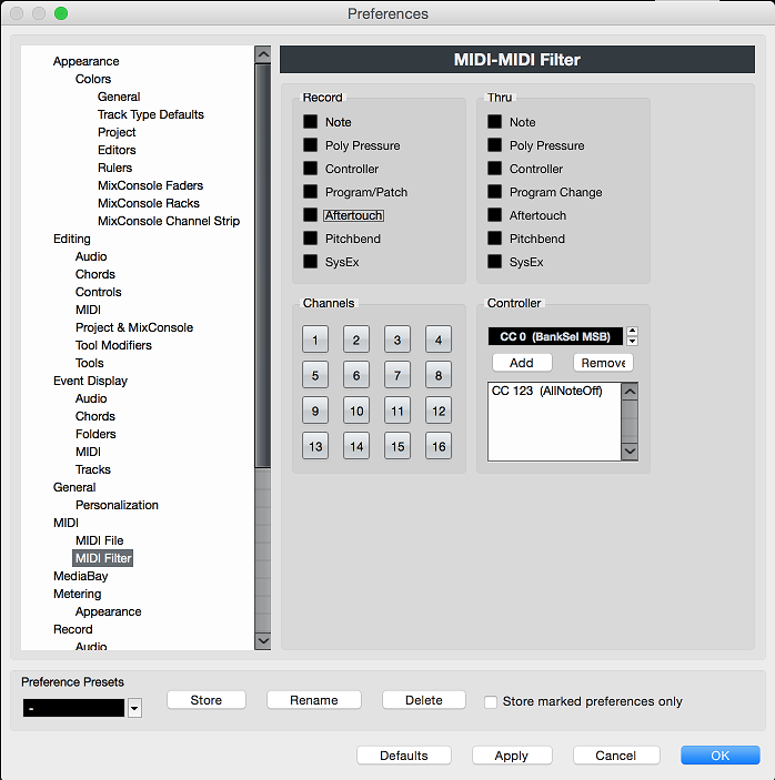 If you have not done so previously, set your Cubase Preferences so that Sysex messages are NOT FILTERED (which is a factory default):
Go to PREFERENCES > MIDI > MIDI FILTER > make sure that SYSEX messages are NOT blocked from being Recorded or passed Thru. If marked, unmark the box for “SysEx”. Click “APPLY”, then Click “OK”
With this Cubase template you can record MIDI (with or without Arpeggio), you can record audio, you can record a combination of tracks – some MIDI, some audio. What you want to learn is how to do what you require. You want to understand how to use this flexible tool. We often get the question, “Can I record MIDI and audio simultaneously?” The answer is yes, but this begs the question “Why?” Of course, your ultimate goal (your project) is always going to determine what you do.
When would you want to record MIDI and when would you want to record AUDIO? And would you ever need to record them simultaneously?
You record data as MIDI because you can manipulate (edit) the data in this format, before committing it to audio. Audio is thought of as your a final goal, while data recorded as MIDI is still being worked on in some capacity. While your data is still MIDI, you can change your mind about the instrument sound that is playing them back – when you render the data as Audio, you have committed to the instrument used. MIDI data is still unfinished, effects are not yet ‘printed’; when you commit to audio you are committing to the effects which get ‘printed’ to the wave. You are committing to a more permanent form of the data. Audio is a format that can be widely distributed, while MIDI data requires very specific gear to playback the music. You must determine – as a production decision – what data needs to be recorded and worked on as MIDI data and what can be rendered (committed) to audio.
You can render audio from your recorded MIDI track, and keep your MIDI Tracks (muted) in a folder as backup “safeties” – in case you ever wish to “undo” and “redo” aspects of your performance. As long as you have the MIDI data, you can create new AUDIO data from them. Think of MIDI Tracks as “works in progress”. Like an artist would use tracings or an outline before committing to the more permanent oils.
Think outside of the box. Do not think you have to always record MIDI first, then convert to Audio (simply because you have always worked that way). MONTAGE is a synth that has the flexibility and resources to let you record as MIDI and/or as Audio as you may design. There are as many as 32 audio bus outputs available – the Yamaha Steinberg USB driver is a dual Audio/MIDI driver that will elegantly allow you to record either/both as you may require. Think about what you want to do with a PART. Do you want to record it in a form because you want to EDIT it? Do you want to simply record it directly as audio? You can record a combination of MIDI and Audio tracks – once you know how each works, you can independently setup what you need. We’ll start with a very traditional workflow that involves recording MIDI Tracks one after the other building up the composition. We will describe the Track layout of this MULTI CHANNEL Template and the basic routing of the MIDI signal and Audio through this system.
If you are going to change and manipulate the data while it’s in a MIDI event stage, by all means, record MIDI Tracks. But recognize you have the option to record audio discreetly for each Part, or you can combine Parts in ways that works for your production. It is wide open!
TEMPLATE IN USE
Let’s view several examples of this template in use – each illustrating a slightly different situation.
Let’s start with “Multi/GM” 16 PART (traditional) one-track-at-a-time sequencing format:
– Press [UTILITY] > “Settings” > “Quick Setup”
– Touch “MIDI Rec on DAW”:
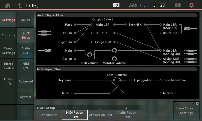
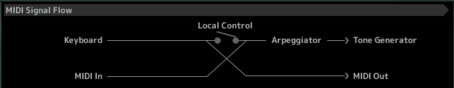
Looking at the MIDI Signal Flow portion of the diagram above, when you play the MONTAGE KEYBOARD, (messages travel left to right) – it is because LOCAL CONTROL is “OFF” (connection is broken) that the signal goes to the MIDI OUT first (which is, in this case, to the DAW MIDI Track); the signal arrives at the active MIDI Track in Cubase (off screen). The setting in the Track Inspector redirects the signal back to the appropriate PART, in the MONTAGE. In this case the signal is sent back to the MONTAGE, on a specific MIDI Channel and arrives in the MIDI Signal Flow diagram above at the MIDI IN. From there you can see it can reach the MONTAGE Tone Generator after passing through the Arpeggiator. (As you can tell in this routing situation the OUTPUT of the ARPEGGIATOR, if any are active, does NOT get recorded to Cubase). As we’ll learn later, the difference between QUICK SETUP #1 and QUICK SETUP #2 is actually where the ARPEGGIATOR is posititioned in this signal flow.
In Cubase, create a NEW PROJECT with the “Yamaha MONTAGE Multi Channel Recording” Template and let’s see how it would be used:
What we will do next is in MONTAGE, activate System Exclusive Messages for the global controllers; namely- the Super Knob and the Scene buttons. And we will add this preference to the MONTAGE “Quick Setup #1”.
First, set the SUPER KNOB CC = OFF and SCENE CC = OFF. Here’s how:
– Press [UTILITY]
– Touch “Settings” > “MIDI I/O”:
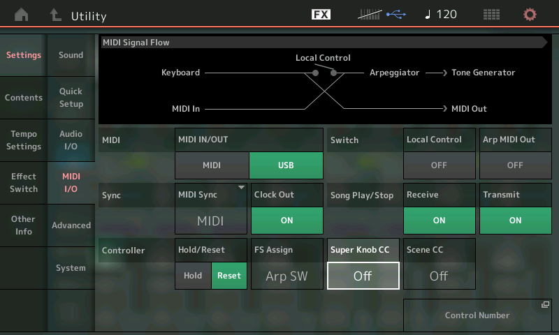
This will cause these devices (Super Knob, Scene buttons) to generate System Exclusive messages Out via MIDI – when the CC Number is set to OFF, the devices generate System Exclusive messages instead of a CC number. Why we are making this change is because, normally, it would merge that CC data with data on MIDI Channel 1 (by convention). By making them System Exclusive, they technically have no channel, the Template will now be able to isolate these on their own Track allowing us to activate and deactivate these global messages separately from MIDI Channel 1 data.*
Each MIDI Track will reject (Filter) Sysex, except the one labeled “Sysex”. Each numbered track will only record the specific one MIDI channel indicated.
*There will be times when you want to have the SYSTEM EXCLUSIVE messages active while you are muting and/or soloing various individual music tracks… to hear how a single Part behaves in different Scenes keeping the control commands on their own track simply allows us the flexibility to keep these commands active independent of any music on Channel 1. By isolating the Super Knob and Scene change commands, as we have done, to their own track, we create a situation where we can independently apply these recorded changes, or not. By activating this track in conjunction with any other MIDI Track, you can isolate just the Super Knob or Scene events for the MIDI Track you want to hear solo’d. You can activate multiple Tracks by using the COMMAND + CLICK on a Mac or CTRL + CLICK on Windows.
Extra Credit: Added in firmware update (1.50 and later) the Utility Mode “Super Knob CC” and “Scene CC” settings can be memorized in the MONTAGE’s QUICK SETUP routines. If you would like to make the Super Knob and Scene buttons send a specific setting (above we have set them to OFF so that they generate System Exclusive messages instead of Control Change messages), you can STORE that condition to the QUICK SETUP. We have been working with the “MIDI Rec on DAW” Quick Setup #1, we have changed the Super Knob CC to OFF, and set the Scene CC to OFF… to Store these changes to the Quick Setup #1 navigate to the “Settings” > “Quick Setup” screen:
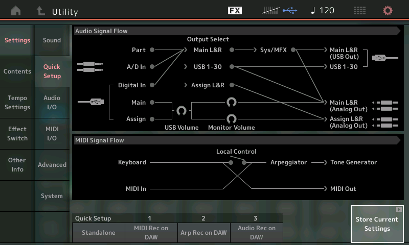
once you’ve made the changes you can simply: Touch the box “Store Current Settings”.
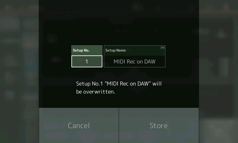
The screen shows SETUP NO. 1 and offers a chance to change the Name, if you desire.
Touch “Store” to update the “MIDI Rec on DAW” setup – this will ensure that the global settings for the Super Knob CC, and Scene CC are stored to this Quick Setup #1. If this is going to be your workflow, it would be wise to store your preferences for Super Knob CC and Scene CC.
The TEMPLATE:
In Cubase, the template opens with a VST INSTRUMENTS Folder (containing Montage Connect), a MONTAGE MIDI Folder, a MONTAGE AUDIO Folder; the MONTAGE Connect utility will initially be opened -make sure “Auto Sync” is ON (then you can close the “MONTAGE Connect” window, it will run and function automatically in the background). You can see the program listed, (screen right), in the VST INSTRUMENTS area: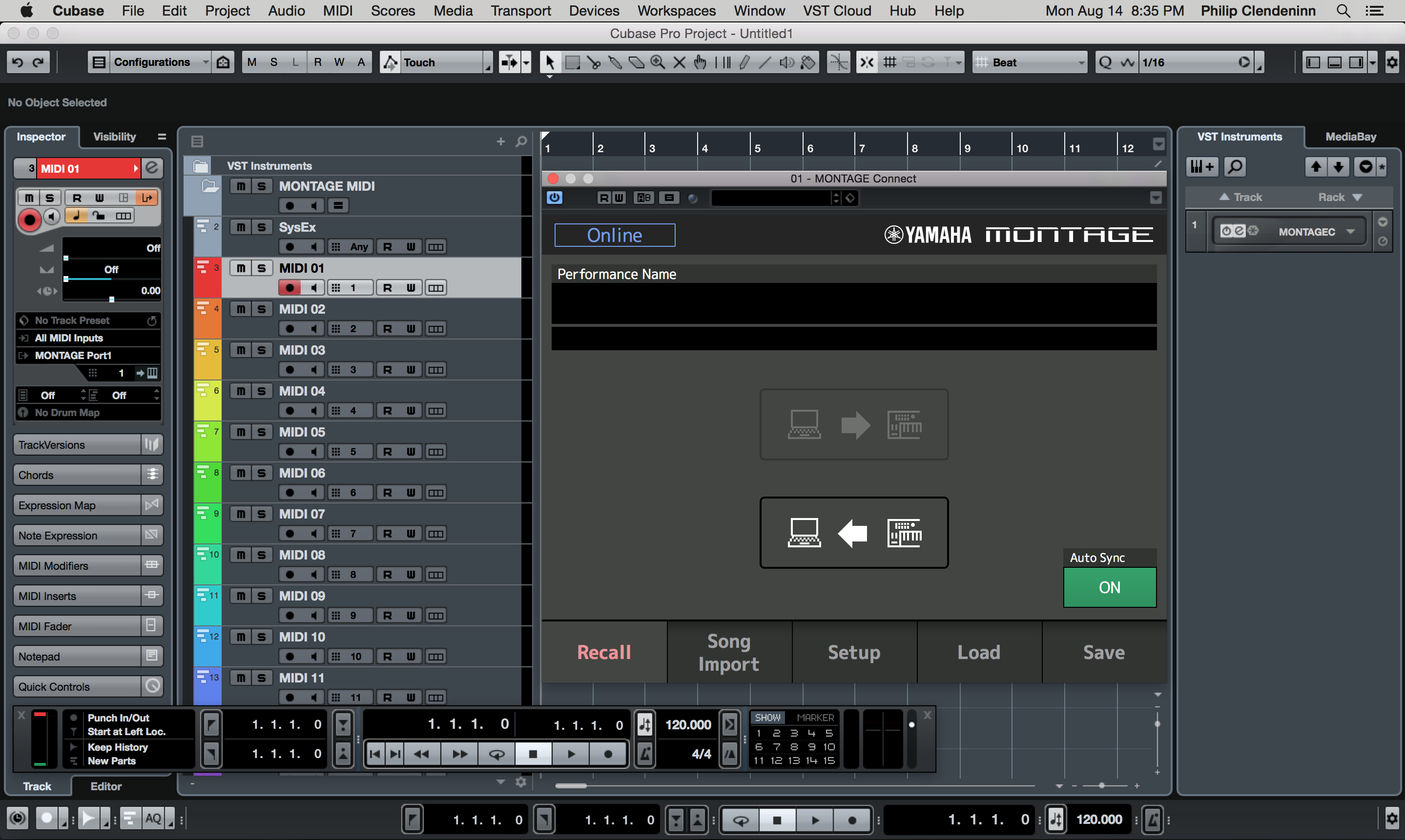
VST Instrument Folder: contains MONTAGE CONNECT – the “Track Lane” here is a pseudo-Track – no data is stored or recorded here, it simply reminds you that the MONTAGE CONNECT utility will be able to automatically capture and restore your MONTAGE Performance. Every parameter is captured and stored with the Cubase Project when you SAVE. The template has the AUTO SYNC = On so that whenever you open your Project, Cubase will automatically bulk dump the Performance you were using at the time back to your MONTAGE’s Edit Buffer. This means you do not have to even have the Performance pre-loaded in your MONTAGE – everything is bundled and stored with your Cubase (.CPR) Project file. This FOLDER can remain closed (as shown above) – MONTAGE CONNECT works in the background, automatically, without you having to mess with it at all.
It is important to know that when you execute the normal Cubase SAVE operation, MONTAGE CONNECT will request a bulk from the MONTAGE hardware – it thus automatically updates and documents the Performance being used your MONTAGE at the moment you SAVE the Project. And you will notice that upon opening that Project in the future will automatically restore the PERFORMANCE to your MONTAGE… Even if the Performance is not in your User Bank, MONTAGE CONNECT will restore every setting.
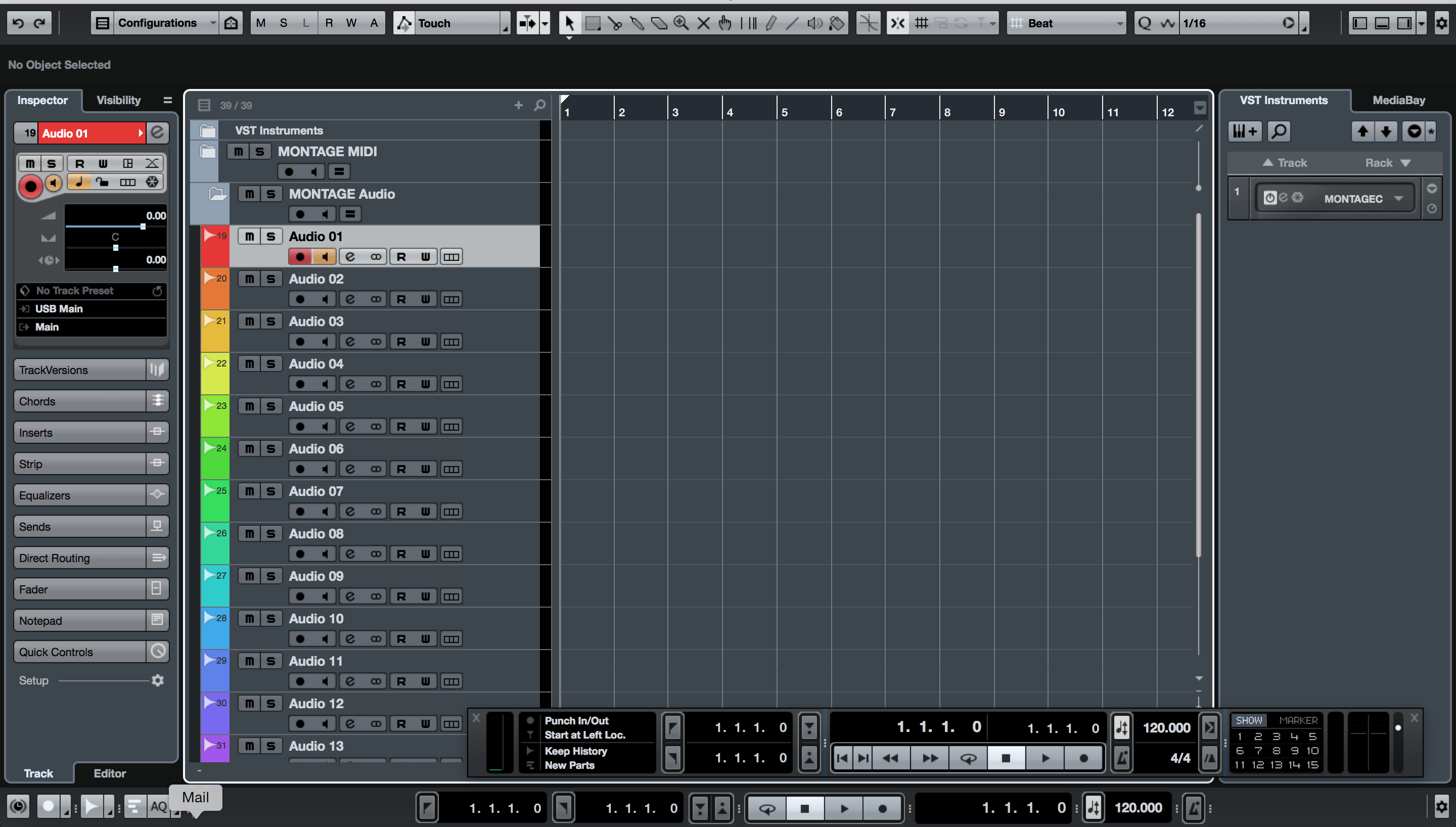
In the screenshot above the VST INSTRUMENT Folder (at the top) is closed. The MONTAGE MIDI Folder is open with its MIDI Tracks: Sysex, MID 01, MIDI 02, MIDI 03 and so on. Offscreen below the MONTAGE MIDI Folder is the MONTAGE AUDIO Folder with its sixteen stereo Audio Tracks.
MONTAGE MIDI Folder: 17 MIDI Tracks (shown above):
– SYSEX Track – The Input Transformer for this Track has been set to reject everything that is not a SYSTEM EXCLUSIVE message. When Record is engaged it will capture all Super Knob movements and Scene button presses.
– MIDI Track 01-16 – Each of the numbered tracks have been setup by their Input Transformer to reject all Sysex messages and to reject all but the one MIDI channel that matches its name. Each MONTAGE Part will transmit directly to and receive data from the correspondingly numbered MIDI Track.
MONTAGE AUDIO Folder: 16 Audio Tracks (shown below):
– Audio Track 01-16 – The Audio Tracks can be used any time you wish to render your data in a permanent fashion. This will require matching a “Part Output” assignment in the MONTAGE hardware, with a target Cubase “VST Connection > Input”, then activating a specific Audio Track to use that Input. Once you are familiar with this signal flow path, everything will start to fall into place. You will be able to make audio recordings whenever you desire.
The 16 Audio Tracks each are assigned a Stereo bus: USB Main, USB 1&2, USB 3&4, USB 5&6 … USB 29&30. You can setup your “AUDIO REC on DAW” QUICK SETUP function in the MONTAGE to configure your PART OUTPUT assignments as best serves your needs. The default has PART 1 assigned to USB MainL&R, _PART 2 to USB1&2, _PART 3 to USB 3&4, _PART 4 to USB5&6 and so on through _PART 16 to USB29&30.
MONTAGE CONNECT window can be opened using the “e” (edit) icon found on screen right in the VST INSTRUMENTS area. This template has it setup so that you do not have to fuss with it at all, it can remain hidden and it will work all the same. What you need to know is that whenever you SAVE the Cubase Project, MONTAGE Connect will “request” and capture the current conditions within your Performance. This is intended to be used to restore the initial start condition of your mixing settings – the Motion Control Engine invites changes across many different parameters – the “initial condition” needs to be captured as a “snapshot” so that all parameters start from the position to which you have set them for the start of the composition. As you can imagine, it’s a type of “reset” – but not just for MW, PB, FC and the usual physical controllers but for every possible parameter in the entire Motion Control Synth Engine!
The concept of the “initial condition” needs to be considered when you SAVE. The idea is you Save when you are closing down working on the Project, simply ensure that before you close, you set the MONTAGE to the condition to which you want it to be restored when next you open this Project. This eliminates you having to STORE the Performance in your MONTAGE. You need only open the Cubase Project and automatically, the data will be bulked via USB-MIDI to the Edit Buffer of the MONTAGE. This works out great, as oft times you may work on a Project over several weeks, making changes, and updating data; MONTAGE Connect will automatically backup and restore every detail as you go.
MONTAGE Connect can be easily deactivated using the “On/Off” button in the VST INSTRUMENTS area (next to the “e” icon that opens/closes the GUI).
Background and Concepts
Here we will learn how MIDI data is routed from the MONTAGE to a specific MIDI Track set to receive the messages. MIDI is a series of coded messages that represent a musical performance. Exactly like the holes punched in the roll of paper that represented a musical performance in an old style Player Piano, the data by itself makes no sound. Your MIDI data by itself is not sound – what gets recorded is just “holes in the paper” – in order to interpret those coded messages you must route that MIDI data to a suitable synthesizer tone generator. MIDI data recorded with a flute sound can be played back as an oboe or as a bassoon. MIDI is not sound.
We have turned LOCAL CONTROL = OFF, if you’re an old hand at MIDI you know that this disconnects the MONTAGE Keyboard from the MONTAGE Tone Generator – so that signal travels to Cubase (to the MIDI Track set to receive it) and is sent THRU back to the MONTAGE Tone Generator on the Channel set by the Track.
Now, the MONTAGE Tone Generator creates the audio. We have literally placed the Cubase MIDI Track in between the MONTAGE Keyboard and the MONTAGE Tone Generator. The Note-on signal must travel through Cubase to trigger the synth, the synth can then return the audio to the Main L&R Outputs which are connected to your sound system. As we will learn, you can also additionally send audio to an audio Input of Cubase. The audio input can be directed to an Audio Track. Both routings are available simultaneously, but you will only monitor (listen to) one of them. You can listen to the MONTAGE direct to its own Outputs or you can listen to the MONTAGE through Cubase – remember Cubase is using the MONTAGE as its audio interface.
This is sometimes where the confusion comes in – usually an audio interface does not have a killer AWM2+FM-X synthesizer built-in, most audio interfaces are separate boxes. Don’t let this throw you – the MONTAGE synthesizer has audio outputs that it uses directly but those same audio outputs are also addressable as the computer’s audio output. The difference is the route traveled. The Direct signal path, MONTAGE-to-Output, is immediate (no latency), the digital audio signal path through the computer is called the latent signal (as the computer takes a few milliseconds to process audio signal), before it is sent back to the MONTAGE audio Outputs.
Since you can choose to monitor either the direct signal or the signal post the computer, you can avoid having to listen to any doubling. We will learn how to choose where to monitor the signal; why and when you would choose one or the other monitor option. Once you are comfortable with this routing scheme, you will notice that the doubling signals will stop being an issue, because you will understand why it happens, and more importantly, you will be armed with enough information to intelligently decide which signal you should be monitoring.
Workflow Routing Summary: Multi/GM
When using the “MULTI/GM” PERFORMANCE setup as a starting point, you are going to be creating MIDI Tracks in the traditional one-track-at-a-time record methodology.
From the HOME screen:
– Press [CATEGORY SEARCH]
– Touch “Init” > select “Multi/GM”
– Press [ENTER]
This template places an acoustic piano in each Part, except Part 10, which is defaulted to a Drum Kit. This is the standard starting point for General MIDI. You, however, are to substitute individual programs for each Part, as you may require. You can put your drums in any Part and in as many Parts as you may desire.
This setup will require that you use the [PART SELECT] numbered buttons, 1-16, to determine which MIDI channel you are transmitting OUT on – in Cubase you simply activate (select) the correspondingly numbered MIDI Track. Because LOCAL CONTROL is OFF, you will only hear the MONTAGE when you have a match between the Keyboard hardware and DAW software. That is, the [PART SELECT 1] button is lit and MIDI Track 01 is highlighted, [PART SELECT 2] is lit and MIDI Track 02 is highlighted, and so on. Remember, the INPUT TRANSFORMER ensures that only one MIDI Channel can properly send data into any particular Track. This is necessary because, as you know, MONTAGE allows you to address multiple Parts, across multiple MIDI channels, simultaneously.
To Record your first MIDI Track, select an instrument for PART 1 in your MONTAGE “Multi/GM” program. After you press [PART SELECT 1] – use [SHIFT] + [CATEGORY SEARCH] to be shown a listing available PARTS.
Set the “BANK” option at the top, to search through specific locations, and importantly, set the ATTRIBUTE = SINGLE
This will narrow your search to PARTs that feature full instrument sounds from your MONTAGE Preset, User, and Library Banks.
Select an instrument for PART 1:
 To hear yourself play this instrument make sure the Track: “MIDI 01” is selected (highlighted) in Cubase. This will ‘complete the circuit’ allowing MONTAGE Keyboard presses to reach the MONTAGE Tone Generator through Cubase MIDI Track 01.
 You are able to ‘hear’ (Monitor) the sound because the MONTAGE (Tone Generator) PART outputs audio to “Main L&R” (Analog Outputs).
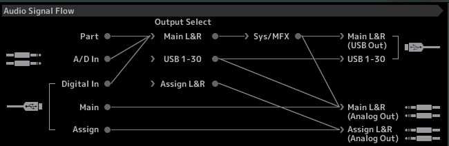
The difference between the MainL&R and any of the thirty numbered USB outputs, is the Main L&R Outs go through the System Effects and the Master Effects, the USB 1-30 Outs do not (meaning the output is discreet) -only the Parts assigned will be routed.
In the diagram of the Audio Signal Flow, you can see that your “Part” is able to deliver audio both to the “Main L&R (Analog Out)” as well as the “Main L&R (USB Out)”. Later we’ll see if you assign a PART to a USB 1-30 Output, it too, can be delivered to the “Main L&R (Analog Out)” as well as the “USB 1-30 Outputs”.
USB Out goes to the computer to be recorded. See the USB cable leads off screen to your computer and Cubase.
Analog Out goes to your speakers to be heard as the direct signal. See the 1/4″ connectors leading off screen to your Monitors.
Audio coming from the computer via USB, is seen arriving via the USB cable (lower left) of the diagram. See the USB cable as returning from Cubase and destined for the MainL&R (Analog Out)
When using the Montage MIDI REC ON DAW default “Quick Setup” all PARTS default to PART OUTPUT = “Main L&R”; You can see in the Audio Signal Flow audio also can travel to the computer via the “Main L&R (USB Out). We’ll pick that up later in this series of articles.
When using a PERFORMANCE like “Moving Floor” which is 6-Parts, 5 Parts under Arp control (see other articles for complete background on this type of Multi-Part, Multi-Arpeggio Performance), the benefits of the MONTAGE Multi Channel Record Template will quickly become apparent. Since each MIDI Track can only record its one designated MIDI Channel, we would need to activate TRACKS 1 through 6 plus the SYSTEM EXCLUSIVE TRACK – placing them all in RECORD READY simultaneously. We will synchronize the CLOCKS so that Cubase is the Master Clock and MONTAGE will be set to follow that clock. All Super Knob movements and Scene change button presses will be documented on the SYSEX TRACK. We will use the MONTAGE Quick Setup ARP REC ON DAW. This will allow those PARTS played directly to pass through to their own MIDI Track, and those PARTS following an ARPEGGIATOR to Output that ARP Phrase as MIDI Data. Local Control is still OFF (connection broken) As you can see below, the Keyboard feeds the Arpeggiator then the signal travels MIDI OUT to Cubase. The data is routed back from Cubase to the MIDI IN and on to the MONTAGE Tone Generator.
In the MONTAGE:
[UTILITY] > “Settings” > “Quick Setup” > select QUICK SETUP #2: ARP Rec on DAW:
This Setup will make the MONTAGE a SLAVE to MIDI Clock.
Extra Credit: Added in firmware update (1.50 and later) the Super Knob CC and Scene CC settings can be memorized as a part of the QUICK SETUP routines. If you would like to make the Super Knob and Scene buttons send a specific setting (in the previous example above, we set them to OFF so that they generate System Exclusive messages instead of Control Change messages), you can STORE that condition to the QUICK SETUP. Here we are working with the “ARP Rec on DAW” Quick Setup #2, you will want to manually set the the Super Knob CC to OFF, and set the Scene CC to OFF… you do so at [UTILITY] > “Settings” > “MIDI I/O”… and then, to Store these changes to the Quick Setup #2 naviage to the “Settings” > “Quick Setup” screen, then execute the change to the “ARP Rec on DAW” setup by touching the “Store Current Settings” box in the lower right corner… then overwriting the Factory “ARP Rec on DAW” Quick Setup.
In Cubase:
– Go to TRANSPORT > PROJECT SYNCHRONIZATION SETTINGS: > MIDI CLOCK OUT > Destination = MONTAGE 1 (Port 1)
– You will set the TEMPO for the recording in Cubase, Montage will automatically follow that Tempo.
Both the MIDI Rec on DAW and the ARP Rec On DAW “Quick Setup” can be used to record MIDI data to Cubase (DAW). The difference is in where the ARPEGGIATOR is located in the MIDI Signal Flow. When you want to document the MIDI phrases generated by the Arpeggio patterns you need to use this setup. In the “Moving Floor” Performance, you have multiple Arpeggios creating NOTE data. Each will write data to its designated Track. Any movement of the Super Knob or changes in the Scene buttons will be documented to the Sysex Track.
We are using “Arp Rec on DAW” – this will write out the ARP phrases as events to the target MIDI Track. This means from this point forward this data is no longer referred to as an Arpeggio, it is now regular MIDI events on the MIDI Track; indistinguishable from regular recorded MIDI events.
To avoid a situation where data playing back from a DAW triggers its Arpeggiator again (this can happen if you decide to continue to add other tracks using “MIDI REC on DAW”) you can activate the ARP BYPASS:
– ARP BYPASS = hold [SHIFT] + [ARP ON/OFF].
– The ARP ON/OFF button will flash indicating Bypass is active.
– To deactivate this ARP Bypass, simply touch the [ARP ON/OFF] button; Light goes steady.
Workflow Routing Summary: Recording Audio, Rendering Audio
While both of the previous MONTAGE “Quick Setup” templates deal with recording MIDI, recording Audio is handled with a separate routing setup. We do not need to place the DAW between the MONTAGE Keyboard and the MONTAGE Tone Generator; instead we want the Local Control to be ON. We want our Key presses to travel to the Tone Generator in a very normal manner. We are interested in documenting the actual output of the Tone Generator as .wav format:
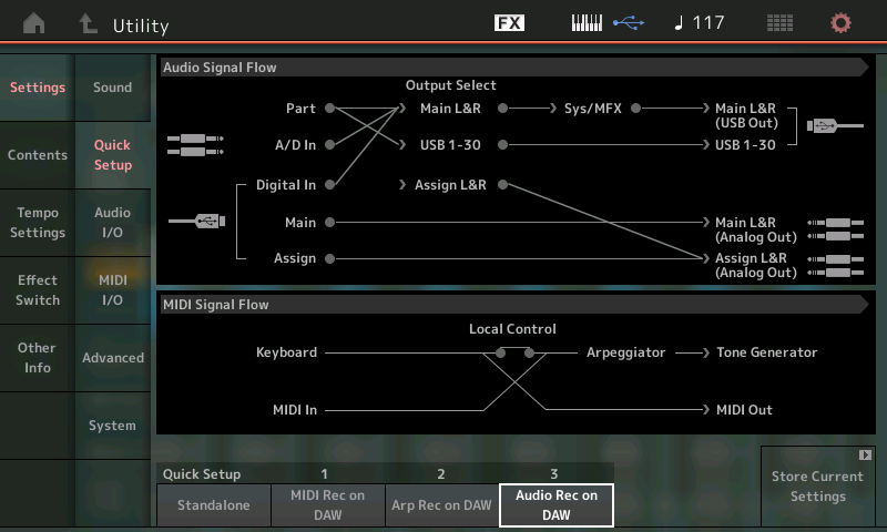
Above you see the Audio Signal Flow and the MIDI Signal Flow diagrams for the default “Audio Rec on DAW” Quick Setup template #3. The Keyboard is routed both to the MIDI OUT and because Local Control is ON, the signal also can travel through the Arpeggiator and on to the Tone Generator. Initially, this QUICK SETUP will activate the DIRECT MONITOR function (bottom right of the Audio I/O screenshot below):
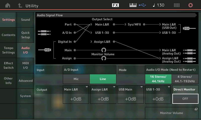
Direct Monitor determines whether or not, signal travels directly to the analog L&R outputs. When it is ON, you hear yourself playing the MONTAGE through the Main L&R (Analog Outputs) – basically, the sound of the MONTAGE will travel its normal path to your speakers. But when recording on the computer, the default condition is to turn this Direct Monitoring OFF. If DIRECT MONITOR is active and you are monitoring through the computer that would be where doubling occurs. The Quick Setup #3 template turns DIRECT MONITOR = OFF. Expect to hear the MONTAGE only after you have your Cubase routing complete – that is, the signal is routed to an active audio track with that Track’s Monitor Switch set to ON. (In a similar way, we are placing the DAW in the signal path and we must “complete the circuit” through the computer).
The audio signal is routed to the Main L&R (Analog Out) in the screenshot above. By arriving back from the Cubase Audio track (the USB cable lower left of the diagram) following left-to-right: MAIN > Monitor Volume > Main L&R (Analog Out):
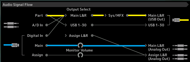 All signal travels left to right; we have colored in the signal flow so you can follow it to and back from the computer: YELLOW is the signal traveling from MONTAGE to the computer; BLUE is the signal returning from the computer and going to the speakers.
You play a PART (yellow line) which is assigned to the MAIN L&R Output, which means it travels through the SYSTEM and MASTER EFFECTS before being routed to the MAIN L&R USB Output. The USB cable (yellow) is going TO the DAW (Cubase – offscreen).
Along the bottom left audio returning from the DAW (Cubase) via USB (blue) is returned to the MONTAGE’s MAIN travels through the MONTAGE’s Monitor Volume and goes to your speakers via the MAIN L&R (Analog Output). Understanding each step in the signal path will help you when you need to troubleshoot – just follow the signal flow.
Alternate Monitor Method
There is another way to monitor yourself and we will explain that below:
If you put DIRECT MONITOR ON, this would mimic the normal setup of the MONTAGE when used “standalone” without a computer connected. Direct Monitor On means the signal goes from the PART to the Main L&R > through the System and Master Effects. In such a routing situation you would need to temporarily MUTE the Cubase AUDIO Track set to record the data, to avoid hearing doubling. Muting the Track does NOT stop it from being recorded… it simply stops it from being sent to the monitor speakers. You can choose to monitor through the computer or you can choose to monitor direct… but you must choose.
Which way should you choose to Monitor yourself?
It is very important that you choose one or the other method of monitoring yourself during the audio recording process. The DIRECT MONITOR OFF (means signal will travel only through the computer) allows you to hear any changes you are applying to the signal in the computer (for example, applying a plugin Effect). The DIRECT MONITOR ON method (with the Audio Track Muted) allows you to hear yourself direct to the output – latency free. And that is the key to the difference – the DIRECT MONITOR OFF means your signal must traverse the computer before reaching the Analog Outputs, while DIRECT MONITOR ON means your signal goes directly to the Analog Outputs (along with being recorded to an audio track, we are just opting not to listen to that audio track, until playback!)
Learn to listen for and recognize doubling. Purposefully double the signal, then correct the situation. You need to tune your ears to what doubling sounds like. While this can differ computer system to computer system, in general, doubling sounds loose, and in worst case scenarios, it starts to sound like flanger or a chorus effect is on. The single signal will sound neat and tight by comparison. Never consider that it sounds good – reason: if you think it does sound good, then you will need to actually create this with the Effects. Right now it’s being caused by a routing anomaly and is NOT being documented anywhere. It is a temporary situation that disappears upon playback. Proper use of the routing situation let’s you, as engineer, listen where you prefer. In general, learn to work with both scenarios – familiarize yourself with how they each work.
Is recording while listening to doubling going to harm your recording?
Actually no, but you still want to learn to avoid it. When recording you want to get a clear idea of what you are getting. If you hear doubling during record, you will notice that it is not there when you playback. This system is like this because you can and should CHOOSE which routing makes the most sense to monitor based on what you are doing.
If you are processing your signal in the computer with a Plugin Effect, then obviously you will want to ‘hear’ that effect being applied. The Effect itself can influence what and even, how you play – so monitoring through the computer, in spite of the latency-situation, is some times the right choice. Your mileage will vary on how much latency the Plugin Effect causes. In most situations, however, you may choose to monitor yourself DIRECT (muting the Audio Track during the Record process), as this gives you the most immediate response and is the ZERO LATENCY Situation.
How the Assignments were made
Next we need to discuss the signal flow from a practical setup standpoint. When you use the default QUICK SETUP #3: AUDIO Rec on DAW, MONTAGE sets up the 16 PARTS so that each PART has its own STEREO bus output. Another important recognition here: when you recall a MONTAGE PERFORMANCE, the PART OUTPUT assignment is recalled as it was STORED in the PERFORMANCE… applying the “Quick Setup” will apply the following reassignment. Please recognize that tapping “Audio Rec on DAW” sends the re-assignment.
The default assignments in this factory Audio Record Setup are as follows:
– PART 1 – Main L&R
– PART 2 – USB 1&2
– PART 3 – USB 3&4
– PART 4 – USB 5&6
– PART 5 – USB 7&8
– PART 6 – USB 9&10
– PART 7 – USB 11&12
– PART 8 – USB 13&14
– PART 9 – USB 15&16
– PART 10 – USB 17&18
– PART 11 – USB 19&20
– PART 12 – USB 21&22
– PART 13 – USB 23&24
– PART 14 – USB 25&26
– PART 15 – USB 27&28
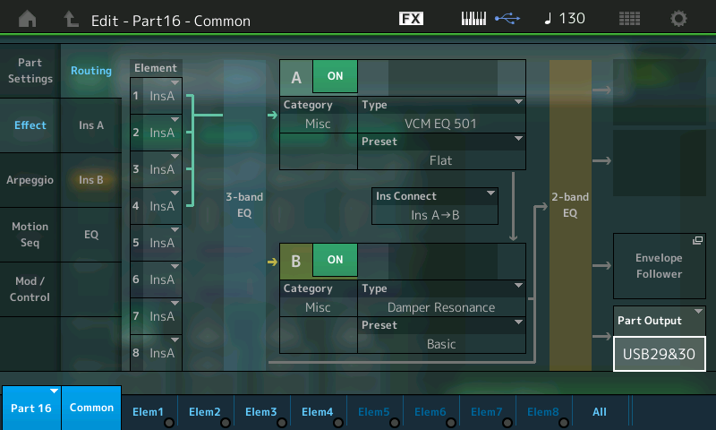
– PART 16 – USB 29&30
We’ll mention again that the only difference between the Main L&R pairing and any of the USB stereo pairings, is the Main L&R can include the System and Master Effects. The significance of this is very important to grasp. The SYSTEM EFFECTs is a “pool” type setup. In other words, the entire community can use it. If you BYPASS the SYSTEM and MASTER Effects, the Main L&R is just another stereo pair – indentical to the others.
Here’s a little background to help you understand how Effect routing evolved like this:
In professional recording studios, before the invention of electronic reverbs, a large hallway or empty space was used as a Reverberation Chamber. The Power Station (a famous NYC recording studio from back-in-the-day) used to use the five story stairwell of the building they were in. At each landing there was a microphone and a speaker – you could adjust the Reverb Time by turning the Microphone On down on level one while feeding audio to the speaker on level 5. Say you routed the snare drum to the REVERB CHAMBER, this literally meant that you would increase the SEND on that channel to feed some of the snare signal into that speaker on level 5. If you activated the microphone on 5 you would get a short Reverb Time and for each level you moved, the greater the Reverb TIME. If you wanted to add Reverb to the Vocals, you would increase the SEND on that channel and feed some of the vocals into the speaker… and so on for each instrument you wanted to reverberate. Yes, they all have the same Reverb TIME (you can vary the amount you SEND, but they all featured the same TIME – the same speaker/microphone combination) – to recreate the sound a band playing in a room, naturally they all have the same Reverb TIME. If you were ever to wander out into the stairwell, you heard a strange mix of instruments – a little bit of snare, toms and hihats, the vocal, but no bass, or kick drum. – just a little bit of everything the engineer want to reverberate. All those signals swimming in the same ‘pool’. The Reverb Return (the signal coming back to the console would be mixed to the main STEREO bus. The amount of RETURN is subjective but typically always less than the Dry (uneffected) signal… “to taste”.
Point being, there is no isolation necessarily in the SEND/RETURN situation – it is a communal pool that all candidates can swim in. The USB Outputs are direct Outputs – they do not go through the SEND/RETURN system. The USB Outputs allow the channel to go to the DAW isolated, if you wish. You can put as many passengers (channels) on any of the buses. They are called “buses” because they are a vehicle for moving signals (in this case) from point A to point B along a specific route. You can have as many passengers on a bus as you desire. You might isolate your signals or combine them in any number of ways – that is entirely up to you.
It was common practice to NOT record with REVERB. It was almost an unwritten RULE – reason was that once you print audio with an EFFECT, it is permanent. And since the communal pool nature of the setup, you might ‘monitor’ with Reverb but not record it. Reverb makes the player more comfortable while performing. Singers, for example, find they have better pitch accuracy when they sing with Reverb (same reason we sound good singing in the shower – the reverberation means the sound hangs in the air for a moment, improving our ability to hear ourselves accurately). And typically the amount of reverb that made the singer comfortable, was often far, far too much for the actual final product. So engineers would wait until the final Mixdown to add (commit to) Reverb.
That’s the history, you of course, can do what ever you like, but the history and evolution of processing can help you understand why certain things are as the are… it does not mean you have to work that way, but just be aware of the history so that what you do has some purpose based on knowledge.
If you would like to use the MONTAGE System Reverb you can – you can print those Parts you want to through the Main L&R bus, and those you wish to treat differently to their own discreet Output and Track.
Let’s see in MONTAGE where the OUTPUT assignment was made by applying the QUICK SETUP #3 template. From the HOME screen:
– Press [EDIT].
– Press [PART SELECT 1]
– Touch “Effect” > “Routing”.
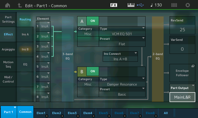
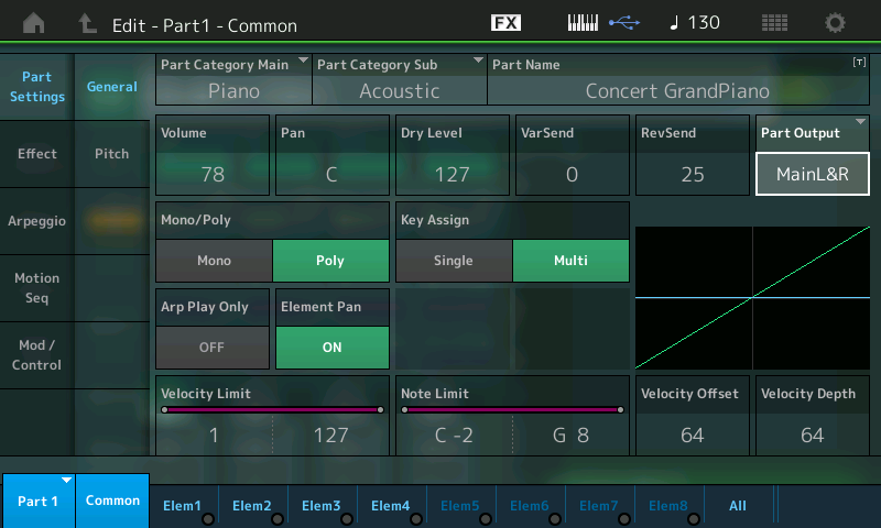
– In the lower right corner of the screen you can see where the PART OUTPUT is set – for each PART, in turn. (The same PART OUTPUT parameter is also found in the upper right corner of the “Part Settings” > “General” screen, as well)
Just because the QUICK SETUP template sets each PART to its own OUTPUT pair, please feel free to change this as you desire or may require.
(You can even store your preference for PART OUTPUT assignments to the MONTAGE Quick Setup #3 (as before).
The reason they did the 16 PARTS to 16 different Stereo pairs for the template is – when you want to actually do this, it would take the longest to setup manually. So naturally, they setup the one that would save you the most time. But remember you do not have to route every PART to its own AUDIO TRACK. You do this because you want to – and hopefully because you have a reason to do so. The fact it is, the template cannot always predict what you will want to do. For example, each PART going to its own discreet OUTPUT is fine for some PERFORMANCES but will make no sense for others.
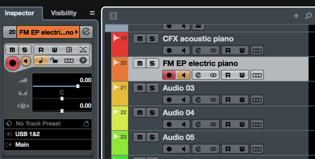
Experiment with assigning PART OUTPUTs for different PERFORMANCES. For example, let’s consider a PERFORMANCE like, “CFX + FM EP”, where PARTS 1, 2, 3 and 4 are the multiple layers of the CFX acoustic piano and PART 5 is the FM EP that you morph to via the Super Knob. You might want to reassign the PART OUTPUTs so that all the CFX acoustic piano PARTS are routed to the same stereo pair of OUTPUTS, and the FM-X FM EP sent to its own stereo pair. Or you might opt to send all to the same stereo pair. But there would be little reason to divide the different velocity layers of the CFX acoustic piano across four pairs of stereo Audio Tracks, if you get my meaning. Changing the PART OUTPUT assignment to suit your needs is the normal workflow – think about what you want to do and proceed accordingly.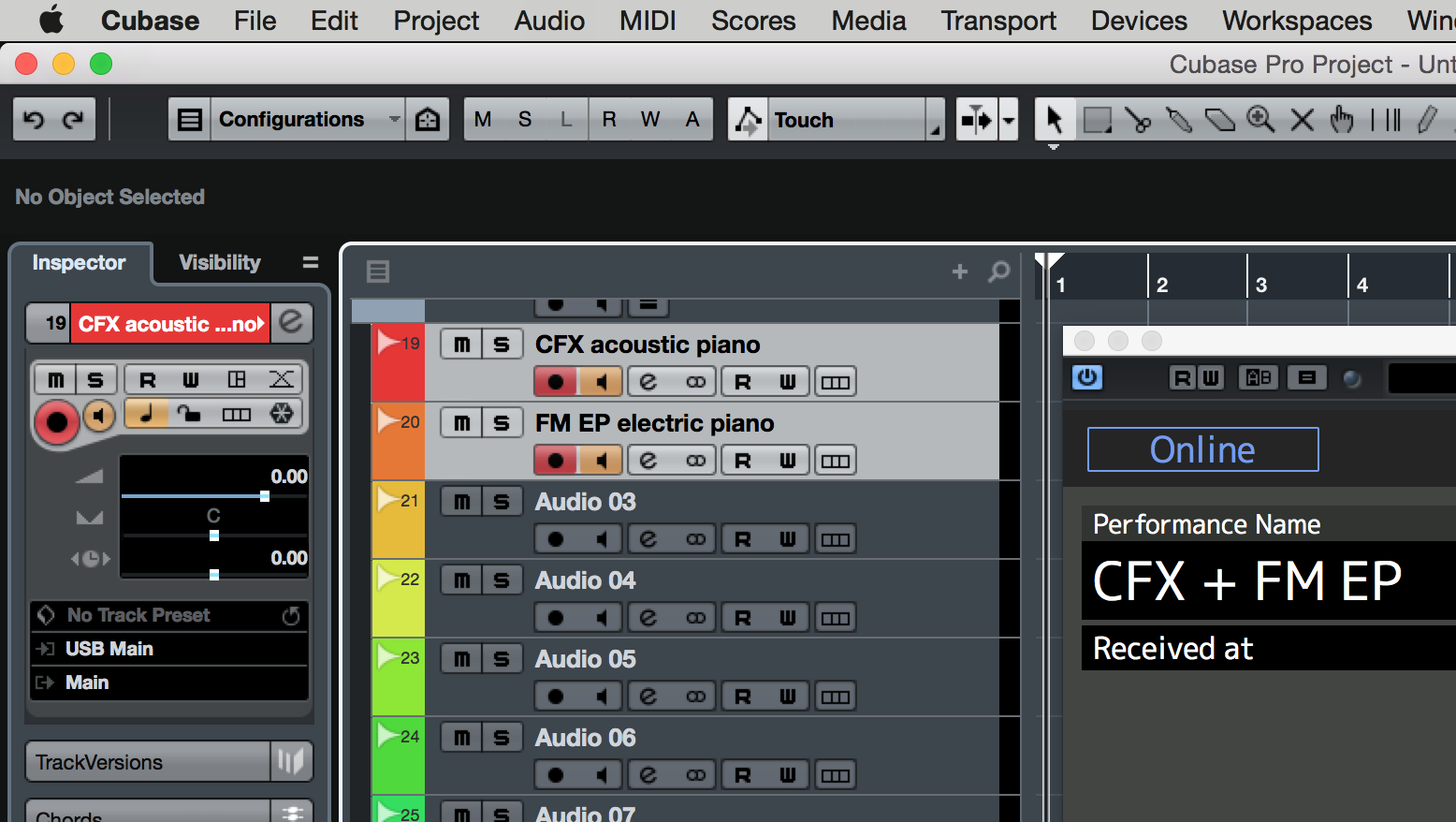 Shown are two active AUDIO Tracks. The first Track is set to record PARTS 1, 2, 3 and 4 (CFX acoustic piano) – each of the four PARTS are set to (USB) MAIN L&R. The second Audio Track is set to USB 1&2 – PART 5 is set to PART OUTPUT “USB1&2”. This is what we refer to as a “production decision” – it really depends on what you have in mind for the recording. Isolating the FM EP on its own stereo pair of audio buses means you can record and then process it separately in your DAW. You might want to apply a special DAW Plugin Effect to just the FM EP portion – that’s a good reason to isolate it on its own Audio Track in the DAW.
 If you don’t plan on doing something like this, then you might opt to send all five PARTS to the same stereo pair. It depends on what you are going to do with the audio in the DAW software. Either way, learning to ASSIGN the PART OUTPUT is a skill worth mastering.
A PART OUTPUT from the MONTAGE is seen as an INPUT by the DAW (Cubase).
Let’s see in Cubase where the INPUTS arrive, and are made available to be assigned to the AUDIO Tracks. (INPUTS to Cubase are in YELLOW, OUTPUTS from Cubase in BLUE)
If you look at the Cubase VST AUDIO SYSTEM: Go to DEVICES > DEVICE SETUP > VST AUDIO SYSTEM:
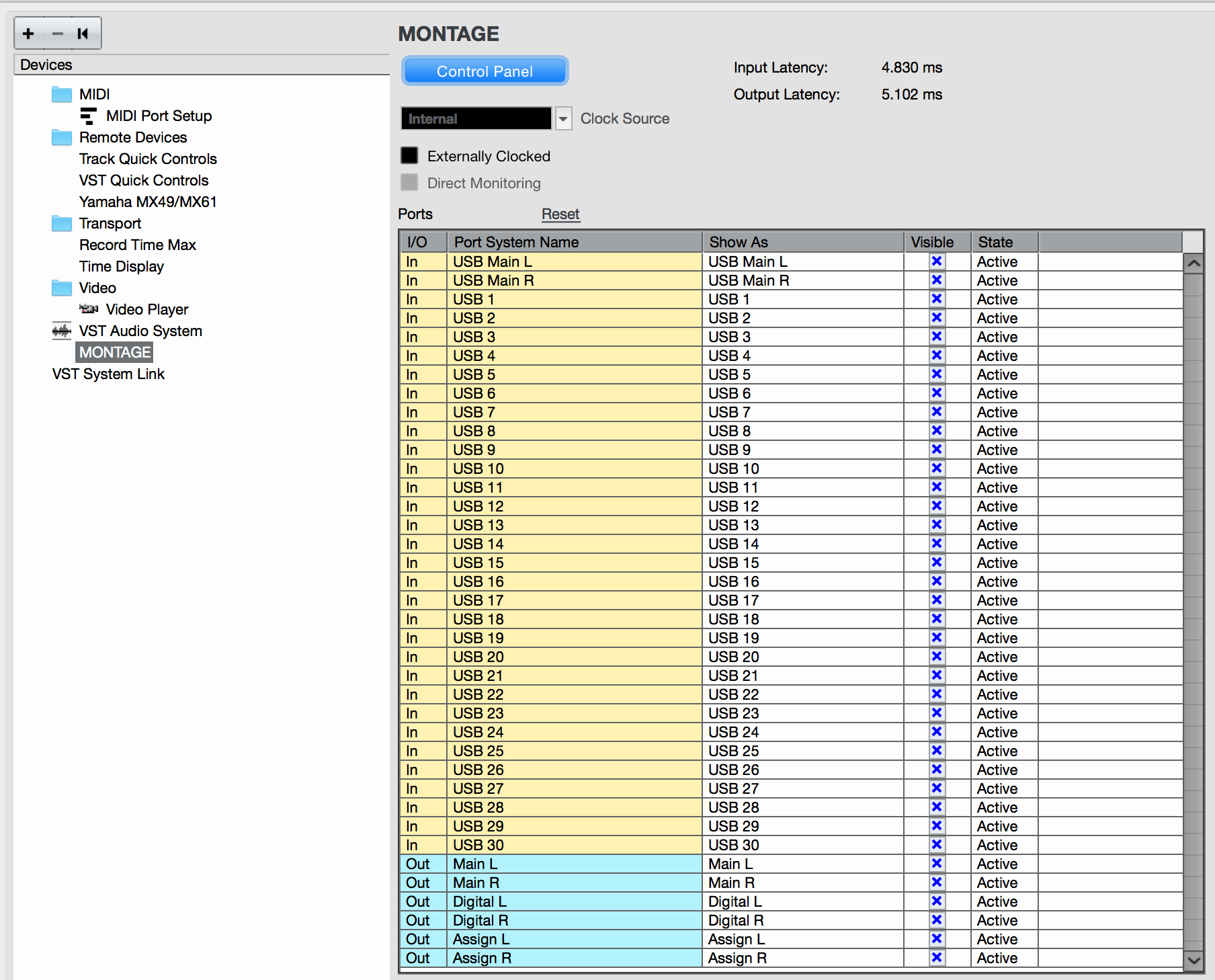
Here you can see the Audio Bus coming from the MONTAGE (yellow) are listed as “In” – MONTAGE OUTPUTS go to Cubase INPUTS.
The “STATE” column will indicate when you have selected to use a particular bus. In the screenshot above all Inputs and Outputs are currently being used.
The final piece of the puzzle is ‘completing the circuit’ by selecting an AUDIO Track that is setup to receive signal on the expected INPUT. Back at the Cubase Track Inspector you can see the INPUT assigned to each Track.
So try it out – and share your experiences on the Forum here.
And check out this lesson from Blake Angelos on the “Moving Floor”.