
Tagged Under
BASIC AUDIO RECORDING PART I
Let’s connect the MOXF6/MOXF8 to your computer and learn about how audio is being routed and how to ensure that the signal is properly received on an audio track. For this basic tutorial all you need are the following:
The MOXF6/MOXF8 connected to your computer via a USB cable (provided)
Install the Yamaha Steinberg USB Driver (YSUSB) version for your particular computer operating system:
* Windows currently at version 1.10.0 (or later)
* Mac currently at version 1.9.10-2 (or later)
* Cubase AI7 (or later) installed and updated
* Install the MOXF Extensions (MOXF6/MOXF8 Remote Tools version 1.0.4)
We will keep this first tutorial basic and forego using the MOXF6/MOXF8 Editor Standalone/VST (for now). This way you can see, learn, and understand how the signal is routed.
In this routing tutorial we will route audio to Cubase from a PERFORMANCE (simple basic) and we will use it to record audio to Cubase. Later we can look at recording MIDI data, first let’s concentrate on AUDIO (after all, it precedes the invention of MIDI by several years!)
Prepare the MOXF6/MOXF8
Press [UTILITY]
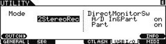
Press [F5] USB I/O (USB input/output)
Set the mode to “2StereoRec“
If not already set this way make sure the DIRECT MONITOR SWITCH for both “A/D In&Part” and “Part” are set to ON.
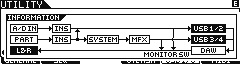
This will allow us to send audio from either pair of MOXF audio buses (USB 1/2 and USB 3/4). An audio “bus” simply is a means to transport audio from one place to another. In the signal flow chart below, you can see that USB1/2 and USB3/4 are being ‘bused’ to the DAW (Cubase).
_ Press [F5] USB I/O
_ Set MODE = 2StereoRec (Dual Stereo Record Outputs)
_ Press [SF6] INFO to view the routing (signal flow)
In our first example, we are simply going to be playing the MOXF while in PERFORMANCE and show how to route the signal to the computer and record to Cubase Audio Tracks.
While in [UTILITY], let’s verify the following MIDI settings:
_ Press [F6] MIDI
_ Press [SF2] SWITCH
_ Make sure that “LocalCtrl” (Local Control) is set to ON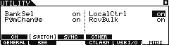
Local Control will allow the MOXF keyboard to trigger the MOXF tone generator directly. We will need this because we are going to be generating audio signal to be sent to Cubase. (AUDIO signal as opposed to MIDI signal).
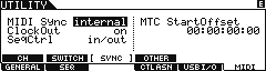 _ Press [SF3] SYNC
_ Make sure that “MIDI Sync” is set to “INTERNAL” and “SeqCtrl” (Sequencer Control) is set to “IN/OUT”
For this basic experiment we want the MOXF to run on its own clock (later we will deal with synchronizing the MOXF’s MIDI clock to the MIDI clock of Cubase)
_ Press [SF4] OTHER
_ Make sure “MIDI IN/OUT” = USB
_ Press [PERFORM]
 _ Call up PERFORMANCE: USR2:051(D03) Dark Continent
Cubase AI Project
We will use Cubase AI in our example but you can pretty much substitute any DAW that can utilize an ASIO driver.
Launch Cubase AI
During the launch you maybe asked if you would like to use the MOXF6/MOXF8 as your Master ASIO device (this will depend on what you have already installed on your particular computer – as Cubase boots up it scans all available drivers for audio and MIDI). Yes, you do. You are asked this because you installed the MOXF6/MOXF8 Remote Tools (extensions). This is important because it will automatically setup the driver and make the important setup functions for you.
Select the EMPTY Template (found under the “MORE” options). This will create an empty Project for this experiment.
Click CREATE.
Verify Port Setup
For this article, let’s verify those settings:
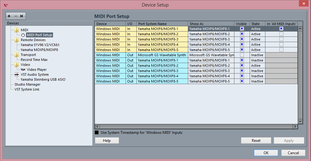
Go to DEVICES (called “STUDIO” in Cubase series 9) > DEVICE SETUP… (“STUDIO SETUP… in series 9) > MIDI > MIDI PORT SETUP (The first screenshot shown below is from a Macintosh computer; the second shows the same for Windows computer. The information will be the same but the look and markings may be slightly different).
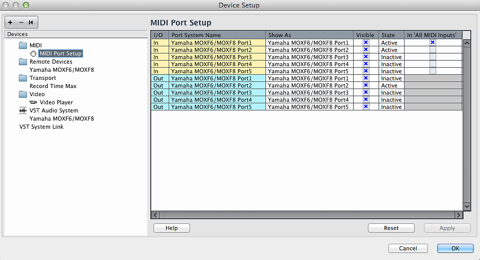
In the “IN ‘ALL MIDI INPUTS'” column – the “Yamaha MOXF6/MOXF8-1” (port 1) is marked. This is the PORT on which the MOXF will communicate musical MIDI data to and receive data from the computer. Only PORTS that are legitimate MIDI INPUT devices should be marked here. Of the Ports appearing for the MOXF6/MOXF8 only Port 1 concerns the MOXF as a Input device. If you connect an external controller device to the MOXF’s 5-pin MIDI IN jack, you would mark “Yamaha MOXF6/MOXF8-3” (port 3). But nothing but the specific MIDI ports that send Note-on, data should be marked!
On this same DEVICE SETUP screen, click on the “REMOTE DEVICE” folder. The MOXF is automatically selected as the REMOTE CONTROL device. Here the “Yamaha MOXF6/MOXF8-2” (Port 2) should be selected as both the MIDI IN and MIDI OUT PORTS. Again, installing the MOX6/MOX8 Extension (part of the Remote Tools package), makes this setting automatically. Port 2 contains MIDI messages that can operate the DAW interface (note-on commands and control change messages are used to open and close screens and operate various functions). These messages need to be kept discreet, this is why it is so important to have the MIDI Ports assigned properly. Strange behavior can occur if you route these MIDI messages to the tone generator or you route tone generator intended messages to the Remote Control layer!
In the “VST AUDIO SYSTEM“ folder, the DRIVER is selected for streaming AUDIO IN and OUT. This is the ASIO Driver.
If you are using a Windows computer the option for ASIO DRIVER may be listed as “Yamaha Steinberg USB ASIO”.
If you are using a Macintosh computer the option for ASIO Driver may be listed by the product name “Yamaha MOXF6/MOXF8”. This is the equivalent setting. The MOXF is acting as the Audio Interface for the application.
If you did not install the MOXF Extensions (REMOTE TOOLS 1.0.1) you will need to make these settings manually. However, installing the Remote Tools should make all these critical settings for you. However, we list them here in case you need to troubleshoot the settings.
Don’t mind the Inactive/Active status column – this will always indicate what resources you are currently accessing. It is not a setting you make here (on this screen) as much as it is a status report of the MIDI port and whether it is currently being used. For example, if you are not using the “Yamaha MOXF6/MOXF Editor VST” at this moment, the status of the Port reserved for the Editor VST (Port 4) will report “INACTIVE”. Only when you launch and are using the Editor VST will the STATE report ACTIVE. Make sense?
Making the Connections
Next, let’s create a connection between the computer and Cubase so that audio we are sending on our two stereo buses from the MOXF can be received in the software. This is done as follows:
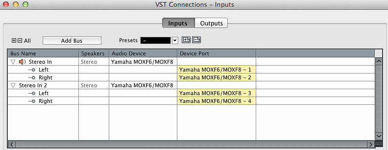
Go to DEVICES > VST CONNECTIONS > INPUTS
Selecting the INPUTS tab makes sense, because we are connecting the MOXF’s two Stereo USB bus OUTPUTS to Cubase’s INPUTS.
Typically, there may already be a “STEREO IN” already created. We can use it if there is, if not, what you will want to do is create a situation where you have two Stereo Bus inputs and have them assigned as in the screen shot below:
“STEREO IN” is set to receive audio from the MOXF on USB 1 and 2
“STEREO IN 2” is set to receive audio from the MOXF on USB 3 and 4
To add inputs you simply click the “ADD BUS” option, and set the attributes you desire. In this case, add 1 or 2 STEREO BUSES, as you require. (Screenshot is from a Macintosh)
Screenshot for Windows: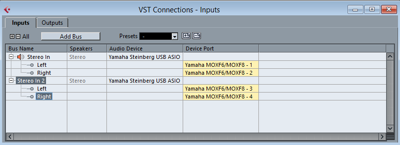
Any time an AUDIO TRACK is set to receive signal from “STEREO IN” it will be receiving audio from the MOXF’s USB 1/2
Any time an AUDIO TRACK is set to receive signal from “STEREO IN 2” it will be receiving audio from the MOXF’s USB 3/4
You will never need any more than these two created INPUTS – no matter how many tracks you record, you simply assign the Track to receive from one or the other for these two inputs. (Think of these as you would real world INPUTS – you simply change the instrument, you plug the instrument you want to record into these inputs as necessary/when necessary).
Return to the main Cubase Track view window. You may want to set the Cubase time counter to count Minutes and Seconds. You do so by either right clicking in the Timeline area, then select “Seconds” or you can go to PROJECT > PROJECT SETUP… > Set the DISPLAY FORMAT = “SECONDS”. Until we establish MIDI communication, the computer counts minutes and seconds.
Next we will need to create two AUDIO TRACKS… one for each of the INPUTS
You can do so by right clicking in the darker grey area on the Track View screen or by going to PROJECT > ADD TRACK > AUDIO
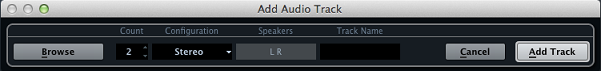
Once you have created these two AUDIO Tracks we can begin to discover how signal is being routed and some of the useful possibilities.
Make sure Track 01 is set to receive “Stereo In”
Make sure Track 02 is set to receive “Stereo In 2”
In the currently selected setup, (2StereoRec), the internal PARTS of the MOXF are routed to USB 3/4, while the A/D INPUT is routed to USB 1/2.
Select the second track, as you begin to play the PERFORMANCE you should hear your playing and see the audio activity meter for Track 02 respond. The RED Record Ready icon routes audio to the track, while the TAN Monitor Speaker icon sends audio back to the MOXF (as audio interface) via USB.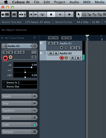
If the TAN Monitor Speaker icon is activated, audio that is returned from Cubase will arrive back in the MOXF and pass through the SLIDER labeled “DAW LEVEL”. You will not need to monitor this audio because you have selected MONITOR DIRECT. (The DIRECT MONITOR SWITCH = ON). On the MOXF6/MOXF8 lower the DAW LEVEL slider. It contains audio after (called “post”) it has traveled through Cubase. If the TAN icon is active and the DAW LEVEL slider is up, you will hear a doubling of the signal – as you are hearing both the DIRECT MONITOR and the DAW Return Level. During record, in most instances, you really only want to hear yourself “direct”.
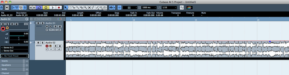
Open the Cubase MIXER. You can do so by either going to DEVICES > MIXER or using the QWERTY keyboard shortcut [F3]
(A third alternative allows you to open screens on your favorite DAW using the REMOTE CONTROL layer – but that is for another article).
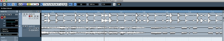
You should see your two audio tracks (AUDIO 01 and AUDIO 02) and the main Stereo Output.
The Faders will be set at nominal 0.00. This is typical when recording, the fader is set open 0.00 – input gain is set at the source (in this case, the MOXF6/MOXF8). Do not touch the Faders in Cubase, set the record level for this channel by increasing or decreasing the OUTPUT level of the source (MOXF6/MOXF8).
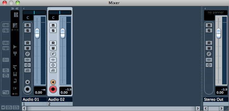
The Mixer will show you the maximum “peak” level reached – in the graphic above this is smaller number: -3.9on the Meter for AUDIO 02.
Level adjustment for this is not made with the main VOLUME Slider on the MOXF6/MOXF8 – in fact, you can pull the main VOLUME Slider all the way down and audio signal is still arriving in Cubase.
Conclusion: The audio that is routed via USB to the computer does not go through the main VOLUME Slider. So “how loud” your speakers are has nothing (whatever) to do with what gets routed to the Cubase audio recorder. We are making this rather basic point for a good reason – it is fundamental to understanding signal routing. The audio that is controlled by the main VOLUME slider is on a different signal path. You can see in the signal flow diagram how the (DIRECT) MONITOR SWITCH routing does not include the DAW (the DIRECT signal flows from the PART through the INS > SYSTEM > MASTER FX then travels through the arrow that points straight down and avoids the USB outputs and the DAW entirely on its way to the main L&R OUTPUTS).
So how do you adjust the overall output level of the MOXF in this case?
You adjust the main OUTPUT VOLUME of the PERFORMANCE:
Press [EDIT]
Press [COMMON]
Press [F2] OUT/MFX
Press [SF1] OUT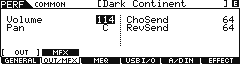
Here you can see the OUTPUT VOLUME of this PERFORMANCE was stored at 114 (on a scale of 0-127). This is where you set the overall output volume of this PERFORMANCE for recording purposes. Try it. Lower this VOLUME and see how it affects the levels arriving in Cubase. Raise this OUTPUT VOLUME as necessary to set your record level. Always use METERS to judge record gain. Always use your EARS to judge the quality of the signal, but not the gain – gain must be set with a METER.
As an experiment. Stop the arpeggiator.
_ On the MOXF: Press [ARP ON/OFF] to turn OFF the L.E.D.
_ In Cubase: Arm Track 2 (Audio 02) and press the RED RECORD button on the Transport.
_ On the MOXF: Press [ARP ON/OFF] to re-arm the Arpeggiator. LED turns ON
_ Record yourself playing the PERFORMANCE.
_ Hit the RED Record button on the Cubase Transport…
When you have completed recording, you can return to the top and playback. In order to hear audio (playback) coming from your DAW, raise the DAW LEVEL Slider on the MOXF6/MOXF8 front panel… It controls the level of all audio coming from your computer. If the DAW LEVEL slider is down you will not hear playback.
Let’s see where the individual PARTS of this PERFORMANCE are assigned to be routed to the USB3/4 audio bus.
Press [EDIT]
Press [COMMON]
Press [F4] USB I/O (USB Input/Output)
You can see how each of the four PARTS of the PERFORMANCE are routed to “3&4”
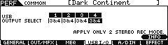
To learn about routing, let’s route one of the PARTS to the other USB audio bus. Move the cursor [>] to the RIGHT to highlight PART 4. PART 4 happens to be the synth pad sound called “P5 Analog Punch” (classic Prophet V type analog pad).
For PART 4: change the USB OUTPUT SELECT = 1&2
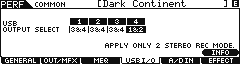
This action will route this PART on its own discreet bus and can now be recorded on its own discreet Track. Let’s take another look at the routing and what we have just done:
We have taken one of the four PARTS of the PERFORMANCE and instead of sending it to the USB3&4 we route it up (the small arrow between “INS” and “SYSTEM” that points upward) to the flow that is feeding USB1&2.
The output level of this PART (P5 Analog Punch) was determined by how well it blended with the “Marimba DX” Voice in PART 3. In fact, its output was determined solely on how it balanced with that Marimba DX sound. You may notice that its impact on the Level meter is somewhat less than when it was in with the other PARTS. Alone it is only a portion of that overall level.
now the question: If you individually raise the level of the “P5 Analog Punch” Voice in order to record it separately, won’t it impact the balance between it and the “Marimba DX” Part when played back? Yes, of course, it will. The “Marimba DX” was original set at a Volume of 127, while this “P5 Analog Punch” PART was set at 112.
Recording each PART to a separate track, undoes the musical balance of the original data. As you attempt tooptimize the record level of each PART you are ungluing the original mix balance. Making the record level optimal, then later in the MIXDOWN process you will need to re-capture that musical mix/balance between the Marimba tone and the Analog Pad tone. We bring that point up specifically for the reason that musical balance is more important that optimized level. If you “unglue” the balance between two sounds, it is now your RESPONSIBILITY when mixing down, to restore that critical mix balance.
Say you wanted to record the DRUMS from this PERFORMANCE to a separate Track. You would set PART 1 to USB 1/2, and leave the other PARTS to USB 3/4. If you want to individually raise the level of the drums, you do so by changing the OUTPUT VOLUME of the PART (PART 1)
Press [EDIT]
Press [1] to select PART 1 parameters
Press [F2] OUTPUT
Press [SF1] VOL/PAN
Try a new recording, route the Drums as a separate STEREO pair to Track Audio 01, while recording the other 3 PARTS to Track Audio 02.
In our next article, we will use USB 1&2 and setup to record a vocal performance to AUDIO 01 and simultaneously record the 4 PARTS of a PERFORMANCE to AUDIO 02. How to route the vocal to a mono track